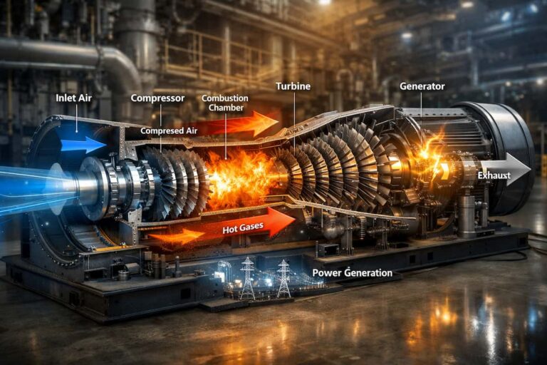
A turbine enclosure brings fuel, hot surfaces, high-pressure oil, electrical equipment and airflow together in a confined space. If a fire starts, delayed detection can turn a small leak or spray into a serious threat to personnel, equipment and generation availability.
Fire detection is the system operators hope never to use. Yet it can be under-tested or treated as a background item on the maintenance schedule. Reliable protection depends on more than having detectors installed: they must suit the fire hazards, remain unobstructed and clean, and communicate correctly with the alarm and protection systems.
For HSE managers, engineers and maintenance teams, that means treating fire detection as a maintained safety function, not simply a box to check during an outage.
Why Turbine Enclosures Are High-Risk Spaces
A turbine enclosure can contain several potential fire sources. The risk assessment should consider the fuel types present, operating conditions, airflow, equipment layout and possible leak locations.
- Fuel-system leaks: A damaged connection or degraded flexible metal hose can release gaseous or liquid fuel. Fuel nozzles, assemblies, check valves and their connections are all part of the wider fuel system that maintenance teams need to inspect and maintain. See GTS’s fuel system components.
- Lube-oil spray on hot surfaces: A leak or failed fitting can atomize oil. If the spray reaches a hot surface, ignition may follow. Oil mist can also coat detector optics, reducing their ability to see a fire.
- Hydraulic-fluid leaks: Hydraulic systems can introduce another combustible fluid and potential spray hazard around auxiliary equipment.
- Enclosure airflow and obstructions: Ventilation, equipment, ducting and access doors can affect detector coverage. A clear line of sight on a drawing may not remain clear after maintenance modifications.
A detector that cannot see the credible fire scenario is not dependable protection. Placement and technology should be evaluated against the actual enclosure, fuels, obstructions and operating environment. A qualified fire-protection professional should review the system design and interfaces.
Detection Technologies Compared
There is no single detector type that fits every turbine enclosure. Selection should consider the expected fire fuels, background radiation, smoke, contamination, temperature, vibration and the detector’s approvals for its installation area.

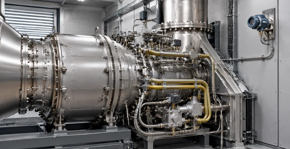
Illustrative image of an industrial flame detector. Select and install equipment to match the approved system design and site conditions.
UV/IR and multispectrum IR flame detectors
UV/IR detectors use ultraviolet and infrared sensing together to identify flame signatures. They can be suitable for some applications, but UV performance may be affected by contamination or conditions that obstruct the detector’s view. UV sensing may also respond to sources such as welding arcs, depending on the detector and application.
Multispectrum IR detectors evaluate infrared signals across multiple bands. Some models are designed for turbine enclosure use and are intended to distinguish fire signatures from hot turbine surfaces and other potential interference. Manufacturer information describes applications that include hydrocarbon and lube-oil fires, and, for certain models, hydrogen or syngas fires. That does not make every IR detector suitable for every fuel or installation: verify the specific detector’s performance data, listings and compatibility with your system.
The Det-Tronics gas turbine enclosure overview provides an example of an integrated fire-and-gas approach, including multispectrum IR detection, gas detection and system controls.
Thermal detection
Heat detectors respond when temperature reaches a set point or changes according to the device’s operating principle. They may provide useful coverage in selected locations, but their placement and response characteristics must match the expected hazard and required response. They should not be assumed to replace flame detection where rapid detection of a spray or jet fire is a protection objective.
Smoke detection
Smoke detection may be appropriate in certain areas, but turbine enclosure airflow, dust, oil mist, temperature and ventilation can affect performance. Confirm suitability for the specific environment with the equipment manufacturer and fire-protection designer.
Carbon monoxide and combustible-gas monitoring
CO monitoring can provide useful information about combustion or process conditions, but it is not a substitute for fire detection. Combustible-gas detection is a separate, complementary layer intended to identify a flammable gas leak before ignition. The detection, alarm, fuel isolation and shutdown functions should follow the site’s documented safety design.
Testing Intervals and Failure Modes
A detector can appear normal while being unable to perform its intended function. Common issues include:
- Dirty or oil-coated optics that reduce the detector’s ability to sense a flame.
- Obstructed or misaligned fields of view following maintenance, equipment changes or enclosure modifications.
- Wiring and connection degradation caused by vibration, heat, moisture ingress, corrosion or mechanical damage.
- Electronics reaching end of life or developing faults that are not recognized promptly.
- Incomplete testing that checks a panel input but does not verify the detector’s response or the full alarm and protection sequence.
Testing intervals should follow the detector manufacturer’s instructions, the site’s adopted codes and standards, applicable authority requirements, insurer expectations and the OEM’s guidance. There is no one testing interval that should be assumed to apply to every detector and installation. Document the basis for the site interval and revise it when equipment, conditions or requirements change.
A disciplined program should include visual inspections, cleaning as directed by the manufacturer, approved functional tests and verification of relevant alarm, fault and cause-and-effect signals. Where the approved procedure allows, test the complete system pathway, including panel indication and required outputs, under controlled conditions. Coordinate testing with operations and suppression-system personnel so that any required isolation or test mode is managed safely, authorized and removed afterward.
Record inspection findings, test results, faults, corrective work, bypasses and return-to-service authorization. These records help maintenance teams identify recurring issues and provide evidence that safety functions are being managed.
The Components to Keep on the Shelf
When a fire-detection component fails, a long procurement delay can leave the plant managing an impairment while awaiting a replacement. A spares plan should reflect the installed system, site risk, lead time and the consequences of a component being unavailable.
Depending on your system and maintenance strategy, consider covering:
- Compatible flame detectors, including applicable Kidde Fenwal models where they are part of your installed system.
- Thermocouples and other sensors needed for related monitoring and control functions.
- Fire-detection wiring, connectors and associated installation spares specified for the system.
- Replacement optical windows or other manufacturer-approved service items, where applicable.
- Test equipment and consumables required by the site’s approved testing procedure.

GTS supplies instrumentation lines that include fire detectors, thermocouples and other turbine sensors. Our sensor product range provides a starting point for identifying your requirements; confirm model, certification, configuration and compatibility against the installed system before ordering. GTS can also help maintenance and procurement teams source suitable turbine components and gas turbine spare parts with responsive delivery.
Compliance and Insurance Considerations
Fire detection and suppression arrangements may be reviewed against applicable codes, local authority requirements, insurer guidance, OEM specifications and the facility’s own risk assessment. Relevant frameworks can include NFPA documents addressing fire alarms and power-generation fire protection, but the applicable edition and site-specific requirements must be confirmed with the authority having jurisdiction and qualified fire-protection professionals.
Insurers may expect a documented inspection, testing and maintenance program, evidence that impairments are controlled, and records showing that deficiencies are corrected. Exact expectations depend on the insurer, policy and facility. Avoid relying on an assumed interval or a generic checklist where site requirements differ.
For further context, see the FM gas turbine guidance and this fire-alarm inspection and testing summary. These resources do not replace site-specific engineering or applicable local requirements.
Build Fire-Detection Spares Coverage Before an Impairment
Effective turbine enclosure fire protection depends on a compatible system, suitable detector coverage, planned testing and timely access to replacement components. A failed or bypassed detector should be treated as a controlled impairment, not an administrative detail. Clear procedures, authorized compensatory measures and prompt restoration help minimize exposure while protecting operational continuity.
GTS can work with your maintenance and procurement teams to review fire-detection spares coverage for your installed turbine instrumentation. Contact GTS to discuss detector models, thermocouples, wiring spares and delivery requirements for your facility.