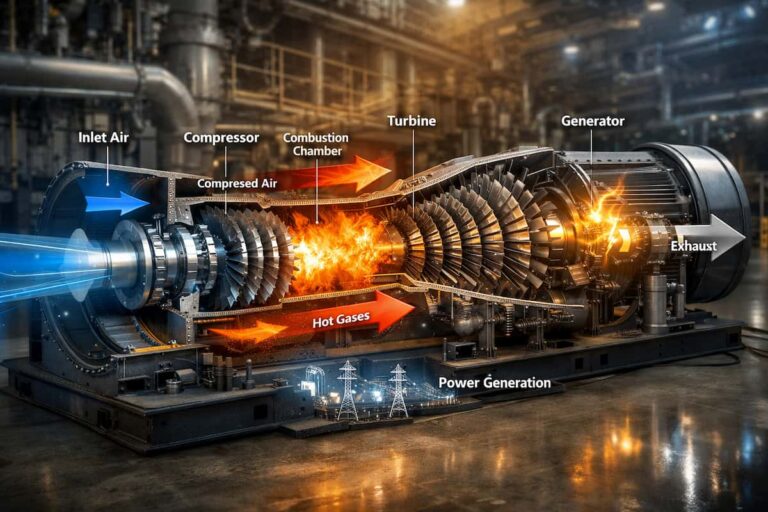
In gas turbine operation, the lube oil and hydraulic systems are the lifeline of the rotating and control equipment. One system protects bearings and gears; the other supplies the pressure needed to position valves and actuators. When either system loses performance, a small fault can become a forced outage.
Yet these systems can be under-maintained because they often look normal from the outside. Oil level may be acceptable while water, particles, oxidation products, or varnish quietly degrade performance. A filter may appear intact while differential pressure rises. An actuator may still move, but respond too slowly during a critical load change.
A disciplined maintenance plan helps you detect these conditions before they affect bearing protection or turbine control. It also gives your team time to source the right industrial turbine parts and plan work around the operating schedule.
How Oil Degradation Turns Into Bearing Damage
Turbine oil must maintain a stable lubricating film between moving surfaces, carry away heat, and protect metal from corrosion. Contamination and degradation weaken those functions.
Common indicators to trend include:
- Oxidation and acid number: Heat and air exposure can degrade oil, increase acidity, and form deposits or varnish.
- Water content: Water can promote corrosion and reduce the strength of the lubricating film. It may enter through seals, oil coolers, condensation, or reservoir breathing systems.
- Particle count: Hard particles can damage precision surfaces and accelerate wear in bearings, gears, pumps, and servo valves.
- Viscosity: Oil that thins or thickens beyond the specified range may not provide the required film strength or flow characteristics.
- Appearance and filter debris: Haze, sludge, unusual color, or metal particles warrant investigation and laboratory analysis.
The damage chain can be gradual. Contaminants circulate through the system, abrade or indent bearing surfaces, and contribute to corrosion or fatigue. As the protective film becomes less effective, friction and heat can increase. Left unresolved, the result may include scoring, pitting, elevated vibration, and bearing damage.
Do not treat an oil sample as a pass/fail snapshot. Trend results over time and compare them with the lubricant supplier’s and turbine manufacturer’s limits. The Mobil turbine oil care guide also emphasizes cleanliness, water control, leak prevention, and regular oil analysis as parts of a complete maintenance program.

The Quiet Failures: Filters, Coolers, and Pumps
A turbine lubrication system depends on components that can deteriorate without obvious external signs. Routine inspection and trend monitoring help find trouble before it affects oil supply.
- Clogged filters: Loading increases differential pressure and can reduce flow. If a filter reaches its bypass or collapse limit, contamination may continue circulating or lubrication may be compromised. Follow the specified element rating and change criteria; do not rely on calendar intervals alone.
- Fouled heat exchangers: Deposits on cooling surfaces reduce heat transfer. Gradually rising oil temperature or a change in return temperature can signal fouling, reduced cooling-water performance, or another restriction.
- Worn pumps and leaking seals: Wear, cavitation, or air ingress can impair pressure and flow. Leaks also create safety, housekeeping, and oil-consumption concerns.
- Reservoir and breather issues: Poor ventilation, moisture ingress, or inadequate oil level can undermine oil condition and system reliability.
Check filter differential pressure, oil supply pressure, reservoir and return temperatures, pump behavior, and leakage as part of your operating rounds. A change from baseline is often more useful than a single reading in isolation.
Hydraulic Control Problems That Cause Trips
Hydraulic control systems rely on clean fluid and predictable pressure to move actuators. Contamination, varnish, air, or unstable pressure can interfere with that response.
A servo valve contains precision clearances. Deposits or particles can cause stiction, hysteresis, sluggish movement, or erratic positioning. An actuator may then fail to follow a demand quickly or smoothly. In a fuel-control loop, that can affect the turbine’s ability to respond to load changes and may contribute to an alarm or protective trip.
Pressure transients also matter. A sudden pressure change can point to a pump, accumulator, control valve, leakage, or restriction issue. The key is to review hydraulic pressure and actuator behavior alongside control-system trends, rather than assuming every response problem is an electrical fault.
The fluid type matters, too. Mineral turbine oil and phosphate-ester electrohydraulic control fluids have different properties and maintenance requirements. Use the limits and procedures for the fluid and servo-valve model installed on your unit. For further background on servo-valve cleanliness and maintenance, consult Moog’s servo-valve guidance.

A Maintenance Routine That Keeps the System Quiet
A practical program combines inspections, laboratory analysis, filtration discipline, and instrumentation checks. Set intervals according to your turbine documentation, fluid type, operating conditions, and site history.
- Establish a sampling baseline. Take representative samples using clean equipment and consistent sampling points and procedures. For critical systems, monthly laboratory analysis can be a useful starting point; increase frequency after contamination events or when results are changing. Daily visual checks and a more comprehensive periodic review can supplement the lab program.
- Trend the right properties. Include viscosity, water content, acid number, particle cleanliness, oxidation or varnish indicators, and filter debris where appropriate. Use a validated method for water analysis and follow the laboratory’s sampling guidance.
- Set system-specific cleanliness targets. ISO 4406 codes describe particle cleanliness, not water content. Confirm the required target with the relevant turbine and servo-valve documentation. Some servo-valve guidance cites 17/14/11 as a general operating benchmark, with 16/13/10 for extended life; these are not universal limits.
- Manage filters by condition. Track differential pressure and replace elements in accordance with approved criteria. After intrusive maintenance or a contamination event, assess whether flushing and offline filtration are needed.
- Control water and heat. Inspect cooler joints, seals, breathers, and reservoir ventilation for likely ingress points. Investigate changing temperature trends and correct the source of contamination before relying on purification alone.
- Verify instrumentation and control response. Check pressure transmitters against expected readings and site calibration requirements. Confirm that vibration sensors and magnetic pickups provide credible signals, and review actuator response, alarms, and filter differential pressure for changes from baseline.
These checks help your team move from reactive oil changes to condition-based gas turbine maintenance. They also help distinguish an oil-quality issue from a pump, sensor, valve, or control problem.
The Spares That Should Never Be Out of Stock
A maintenance plan is only as useful as the parts available when an inspection reveals a problem. Review critical spares against failure history, lead time, turbine configuration, and the consequences of a delay.
Depending on your equipment and maintenance scope, your list may include:
- Accessory gear and thrust bearings
- Oil seals and deflectors
- Compatible filter elements and seals for filter housings
- Pressure sensors and transmitters
- Vibration sensors and magnetic pickups
Confirm part numbers, ratings, materials, and configuration against the applicable documentation before ordering. A substitute that looks similar may not meet the operating requirements of the system.
GTS supplies OEM-equivalent bearings and deflectors, including accessory gear bearings, accessory thrust bearings, oil seals, air seals, and deflectors. GTS also distributes instrumentation such as pressure sensors, pressure transmitters, vibration sensors, and magnetic pickups. Explore the GTS Bearings & Deflectors range and Sensors range. Availability and delivery depend on the part and application; share your turbine model and part details so the team can review your requirements.

Protect Reliability with a Planned Spares Strategy
Lube oil and hydraulic problems rarely announce themselves with one obvious sign. A particle-count change, rising filter differential pressure, unexplained temperature shift, or sluggish actuator may be the first indication that the system needs attention.
Consistent sampling, system checks, and the right replacement parts help minimize the risk of bearing damage and control-related trips. For related guidance, see GTS’s article on turbine bearing failures and its gas turbine sensor selection guide.
If you are preparing for an outage or reviewing your critical spares, contact GTS to discuss a lube and hydraulic system spares kit. Our team can work with your maintenance and procurement staff to review the relevant turbine components and support a dependable parts-sourcing partnership.