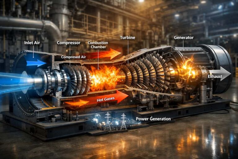

Heat rate creep is easy to miss on the control room floor and hard to miss on the fuel invoice. A turbine can meet its dispatch target while consuming progressively more fuel to produce the same output. Every increment of degraded efficiency is fuel cost carried forward, day after day.
The change is often gradual, with no single alarm identifying the cause. Fouling, seal leakage, fuel system issues, and instrument drift can all contribute. Tracking corrected performance trends helps your team distinguish a real mechanical loss from changing operating conditions, and plan corrective work before the next outage window closes.
What Heat Rate Creep Actually Is
Heat rate is the amount of fuel energy required to produce a unit of electrical or mechanical output. When heat rate rises, the turbine needs more fuel to deliver the same output; its thermal efficiency has declined.
Heat rate creep describes this gradual deterioration over time. It can accumulate between inspections as deposits build on compressor airfoils, clearances change, seals wear, or fuel nozzles become restricted. Changes in ambient temperature, load, fuel composition, and measurement accuracy can also affect the number, so raw readings alone do not establish a mechanical problem.
A reliable comparison starts with a defined baseline (often a clean, post-maintenance operating condition) and corrects performance data for relevant site and operating conditions. For formal acceptance or comparative testing, use a consistent procedure aligned with ASME Performance Test Code 22, rather than relying on an informal calculation.
The Mechanical Causes
Heat rate deterioration is rarely explained by one component in isolation. Patterns across the compressor, combustion system, seals, and instrumentation help narrow the investigation.
Compressor blade fouling and tip clearance growth
Dust, oil mist, and other airborne contaminants can foul compressor rotor and stator blades. Deposits change the airfoil surface and reduce compressor efficiency and airflow. The turbine may then produce less output for a given fuel input, or need more fuel to maintain the required output.
Tip clearance matters too. As clearances increase, more air can leak around blade tips instead of following the intended flow path. Wear, erosion, rubs, thermal effects, and assembly condition can contribute. During inspection, teams may also check related hardware (such as shims, keys, and spacers) against the applicable fit and clearance requirements.
A compressor review should consider blade condition, inlet condition, variable geometry, and operating history together. GTS provides gas turbine compressor parts and additional guidance on compressor maintenance and spare parts.

Seal wear and leakage
Labyrinth and brush seals help control leakage between sections of the turbine. When their condition or clearances deteriorate, leakage can reduce the amount of air or gas doing useful work. Air seal degradation can also disrupt secondary-air flows used for cooling and sealing.
The performance impact depends on seal location, condition, and turbine design. Inspection findings and performance trends should therefore be assessed together rather than treating every seal leak as an identical efficiency loss.

Fuel nozzle plugging and poor combustion
Fuel nozzle deposits, wear, or flow variation can disrupt fuel delivery and combustion uniformity. The result may include uneven firing, higher exhaust temperature spread, emissions changes, or operating constraints that affect efficiency. A nozzle issue is one possible cause of high spread, not the only one. Sensor faults, combustion hardware condition, and other flow-path effects should also be considered.
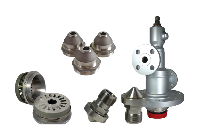
Fuel nozzles and assemblies should be evaluated and serviced in accordance with the turbine’s approved maintenance procedures. GTS supplies fuel system components, including nozzle assemblies and related parts.
Instrument drift and temperature measurement
A drifting thermocouple can make exhaust temperature data misleading. Depending on the control and monitoring scheme, inaccurate readings may obscure a developing issue or influence operation. Inlet temperature measurement matters as well: incorrect input data can distort corrected performance calculations and make a healthy turbine appear degraded, or mask an actual decline.
Trend individual channels alongside the temperature spread. Check sensor condition, wiring, calibration, and signal plausibility before attributing a change solely to fuel nozzles or other hardware. Learn more about gas turbine sensors and high-temperature sensor selection.

How to Track It
Build a repeatable trend using reliable instrumentation and comparable operating periods. A practical monitoring program includes:
- Corrected heat rate and fuel flow versus output: Compare stable operating periods using the same fuel-energy basis and appropriate corrections.
- Compressor discharge pressure and temperature: Evaluate these with inlet conditions, load, and other relevant operating data. Pressure alone is not a measure of compressor efficiency.
- Inferred compressor efficiency and airflow: Use the plant’s validated performance model or test procedure to identify meaningful changes.
- Exhaust temperature mean and spread: Watch for persistent changes and outlying thermocouple channels; investigate rather than assuming a single cause.
- Operating context: Record ambient conditions, fuel composition, load, inlet pressure loss, variable guide vane position, bleed status, and recent washing or maintenance.
Set review intervals that fit your fleet, operating profile, and site procedures. Compare stable-load data at consistent intervals and review it before and after relevant maintenance. The ASME PTC 22 framework is useful for formal gas turbine performance testing; diagnostic studies also emphasize correcting for operating conditions and using multiple indicators to distinguish causes (gas-path diagnostics review).
What Parts Restore the Loss
The right replacement depends on inspection and diagnosis. Replacing parts without identifying the mechanism can add cost without recovering performance. When findings confirm component degradation, relevant replacement categories may include:
- Compressor rotor and stator blades where inspection identifies damage or wear.
- Gaskets and seals to address confirmed leakage or sealing issues. Depending on the application, this may include Flexitallic, copper gaskets, C-seals, E-seals, brush seals, and labyrinth seals.
- Fuel nozzles and assemblies where testing or inspection identifies plugging, wear, or unacceptable flow variation.
- Calibrated sensors, including thermocouples, when measurement drift or failure is confirmed.

For any part, verify model, configuration, material, dimensions, and applicable OEM specifications before ordering. An OEM-equivalent part can be a practical option when it is appropriately qualified for the application. Availability and delivery depend on the specific part and configuration; early sourcing can help avoid letting procurement lead time dictate outage scope. Explore GTS’s approach to OEM and OEM-equivalent turbine parts.
When to Act
Act when corrected trends show a persistent decline, when inspection identifies a confirmed defect, or when multiple indicators point to the same component. Coordinate corrective work with planned outages where possible, allowing time to complete engineering review, verify part requirements, and secure critical spares.
Waiting another inspection cycle can mean continued excess fuel consumption and a narrower window to plan repairs. If an underlying issue progresses, it may also increase repair scope or constrain operation. The actual financial impact depends on unit output, fuel price, dispatch, and the measured performance loss, so quantify it using your plant’s operating data rather than a generic estimate.
Turn Performance Trends into a Recovery Plan
Heat rate creep is manageable when performance data, inspection findings, and parts planning inform the same decision. That requires trustworthy measurements, a clear baseline, and disciplined follow-through from diagnosis to outage execution.
GTS works with plant performance and maintenance teams to identify suitable OEM-equivalent turbine parts, including compressor components, fuel system parts, seals, and sensors. Contact GTS for a performance-recovery consultation to discuss your turbine model, observed trends, and upcoming outage requirements. Start the conversation with GTS.